INTRODUCTION
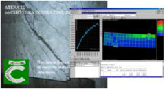
Design of the concrete tunnel lining was performed using nonlinear finite element analysis in the commercial software package ATENA developed by Cervenka Consulting company . The important interconnection of the separate railway stations located in the eastern part of the city (Libeň, Vysočany and Holešovice railway stations) with the central city area ones (Main Station and Masarykovo Station) was completed relatively recently.
The Vítkov tunnels are the substantial and integral part of extensive and exceptional construction called “The New Prague Connection”. The New Connection not only solves the interconnection of the central railway station for the through high-speed railway system but simultaneously provides the recently impossible connection of the commuter and intercity systems across the city.
NONLINEAR ANALYSIS
Realistic analysis of structural response in ATENA is based on nonlinear constitutive models taking into account all the important aspects of concrete behavior in compression and in tension. Cracking is controlled by tensile strength of concrete, crack opening and crack width depends on material fracture energy. Concrete in compression is described by a plasticity model that reflects compressive crushing in multi-axial stress state and influence of lateral stresses to the compressive strength, the so called confinement.
Final lining in the bored part was designed from plain concrete C 25/30. The material parameters used in the numerical analysis correspond to this concrete quality. A tunnel section of 1 m length was modeled in plane strain idealization that well describes the state of the lining in the tunnel inner sections.
An important aspect of the lining behavior is its interaction with the surrounding ground. The structural model was supported by springs around the tube and under the abutment; spring stiffness was derived from ground properties. Alternatively, the Drucker-Prager plasticity material model was used for modeling of surrounding ground by quadrilateral finite elements.
For the nonlinear analysis the lining was loaded in incremental steps by dead load, shrinkage, non-uniform temperature fields representing summer or winter conditions, and finally by ground pressure until structural failure.
CONCLUSIONS
Railway tunnels under the Vítkov Hill represent a unique structure from the point of view of its extent, design methodology, construction and its significance for railway traffic inPrague.
The unreinforced tunnel lining was designed with support of nonlinear finite element analysis. Both these methodologies, i.e. tunnel lining made from plain concrete, and nonlinear analysis based design, are rather novel, at least in theCzechRepublic. The presented combination of them was very successful and represents an accomplishment and extension to the usual design procedures according to codes.
Experience from this project shows that the utilization of progressive methods supports an optimal structural design, and in final effect it leads to broad and significant savings during construction. The structural properties were sufficiently verified and confirmed. Simultaneously, preconditions were created for savings of material (steel reinforcement) and for reduction of work demand in comparison to the usual reinforced lining.
Get the latest information about new products, updates and releases.


